Check this out:
Looks delicious, doesn't it?
What you see here is not a result of a fluid simulation. It's a combination of Linear Algebra and some neat mesh manipulation tricks to make the surface deform and behave as if it were a small body of water in a container reacting to being thrown around a scene, sloshing and splashing back and fourth.
This is what you call a rig. A "sloshing liquid rig" as I decided to name it. Intended to be used in a couple of scenes of the animated short film I'm working on.
This bad boy will save me so much time when I get to animating liquids for background objects.
Let's now dive in and see what's happening under the hood. There's some math involved, but be not afraid: as always, I will try to make it as entertaining as possible and visualize everything along the way.
Preamble
I'm a fan of CG physics simulation. I mean, if you've read some of my earlier blog posts you can probably tell.
As the time goes on and the new techniques and Software become available, fluid, soft-body and rigid-body sims for "cinematic" CG become more user-friendly, feature-rich and efficient. Alas, I have to repeat myself by stating the obvious once again:
Simulations are hard.
It takes time to set-up, direct, fine-tune and output any production-level simulation.
Still, apart from the obvious need for serious computing power a lot of disk space to store the positions of those tens of thousands of particles, the biggest issue for me personally is the "fragmented" nature of CG simulations in general. It's messy, that's what it is! There are tons of files, directories, different takes, versions e.t.c. you have to manage for each shot, and each scene.
Let's take a look at the most basic set of steps required to produce a CG-animated segment with a small-scale fluid-simulated mesh:
- Prepare meshes suitable for the solver you are using (with required mesh complexity, structure, thickness, normals direction e.t.c.)
- Set up fluid emitters, fluid parameters and surface collision properties.
- Simulate. Then tune. Then simulate again. Rinse and repeat until out of time and/or budget.
- Re-simulate the final take or two and cache. I mean, you're not really planning to simulate and mesh thousands of fluid particles during rendering, right?
- For some meshers out there if you wish to see motion blur on the deforming mesh you will also need to include motion vectors for each particle when caching the results of the simulation which will increase disk space used by your cached simulations.
- Take those point caches into a mesher of your choice. Set up meshing parameters until an optimum between mesh complexity and captured surface detail is achieved.
- Cache that mesh. I mean, you're not really planning to mesh thousands of fluid particles during rendering, right?
- Load the cached mesh into your scene, set up materials and finally render!
 Holy wave of complicatedness, Batman! Run!
As a project manager I believe that every element should have its time and place, serve to satisfy specific requirements as well as be time- and cost-efficient.
For "hero" objects (those which take most of screen space or are directly involved with the plot) full-fledged simulation is a necessary evil: you want to dazzle your viewer with the most realistic and spectacular visuals (and maybe even get noticed by the Big Dogs along the way).
And the background objects? Meh... Anything goes for those. If it looks even half-decent it will do just fine. Taking limited time and budget into consideration you'd rather focus on your primary subjects and minimize the time spent on the decorations and "nice-to-haves" as much as possible so as not to affect the creative process or prolong the duration of the project development stage too much.
A plethora of possibilities
I gotta be honest. This was my third attempt at creating such a rig. Naturally, in VFX there are many ways to achieve the look you're after and you need to go through a bit of research and development to come up with an optimal solution.
These are the ones that I came up with while working on different iterations of the rig:
- Booleans
- Skeletal animation
- Blend shapes
- Surface reprojection (used in the final version of the rig)
These were the techniques I tried out in an attempt to produce a basic dynamically changing mesh which would then go through several stages of deformation to add more randomness and realism to the final animated surface of the "liquid".
Before we go any further, I should point out that I will be using XSI Softimage to produce the rig, as it is my main 3D DCC package. Still, the ideas and concepts I use can be reproduced in most of the contemporary off-the-shelf 3D animation packages (as well as real-time game engines).
Now let's go and rig ourselves some "liquid".
Booleans
As obvious and trivial as the sky is high, this solution was also the worst of them all.
Those who have experience working with booleans in CG probably know the main reason for anyone to re-think using booleans in production: boolean operations produce ugly meshes.
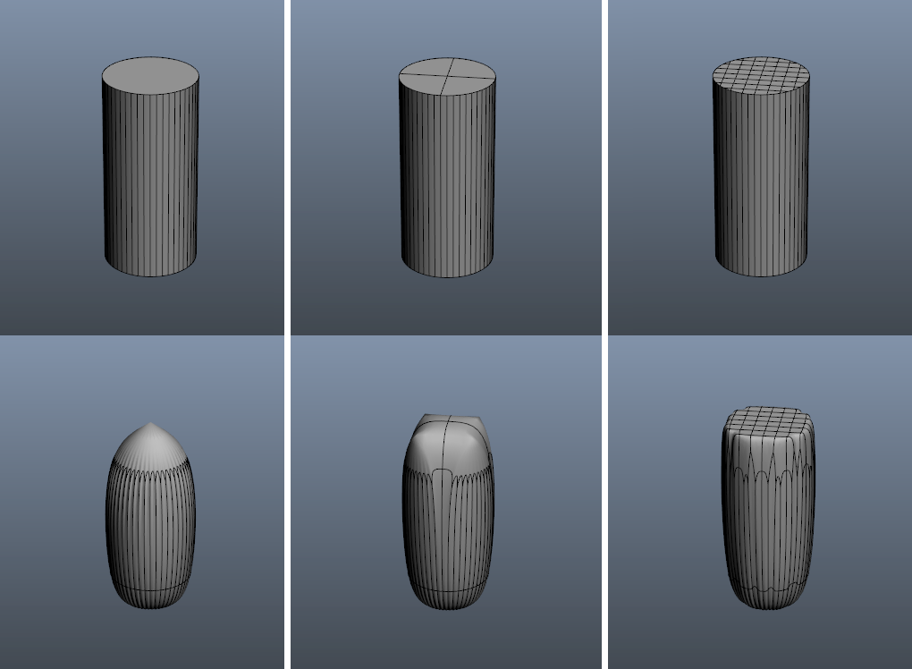
In the video above I've set the cube that was used to shape the top part of the new "liquid" mesh to 1 quad per side. The resulting n-gon is what you get after the boolean operation. It's a dead end: no subdividing allowed. And if you dare to, here's what you'll get at various cube mesh densities:
To make things worse, there is no possibility to create a weight-map for the resulting mesh since it's being re-created each frame (well, not without some complicated mesh-to-mesh distance-based transfer trickery). And weight-maps will become important as we go on, since they will let us shape additional deformations to make the rig look and feel more like the "real thing".
Because of these limitations and shortcomings I'll leave this technique alone and will keep looking for a better solution.
Skeletal animation
Another rather obvious solution: skin the top part of the mesh to a bone or a null object!
Now simply manipulate the bone to give the "fluid" mesh required shape! Success!
Yeah, right. If only things were that simple... When rotated the bone allows to shape the top of the "fluid" mesh but this comes with a bit of an issue:
Now have a visible loss of mesh volume and a "lip" where I placed a loop to sharpen the edge. I'll remove the loop and specify crease angle to compensate. I will then try and non-uniformly scale the bone along one axis to compensate for the lost "volume" of the mesh. The result looks... good!
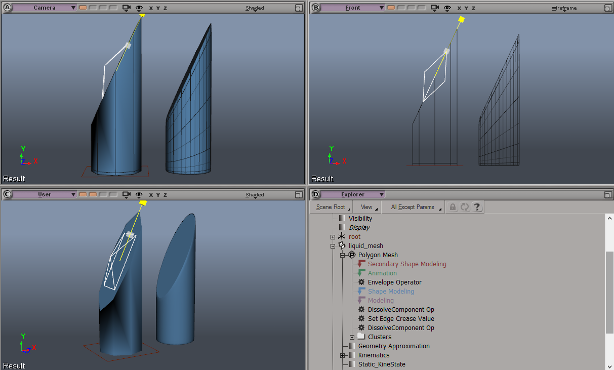
The only problem is: X-scale to X-rotation correlation to maintain mesh volume is non-linear and looks like this (I stopped at 75-degree rotation because there's really no point in going any further):
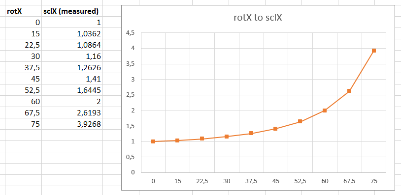
Looks familiar, no? We have some sort of a correlation that looks similar to that of a power equation. I tried approximating it using a quadratic function and came up with the following basic expression: (0.016 * x)2 + 1.
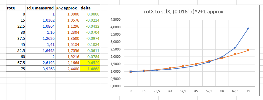
My approximated quadratic function obviously can't help with the extremes over 60 degrees and produces a noticeable error for most intermediate values:
Since I'm lazy, to produce a more precise approximation I will just use MS Excel and fit a polynomial curve onto the gathered data-set. You can see the resulting polynomial function below:
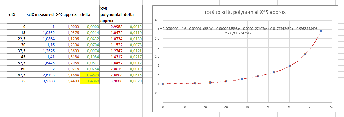
The error is now tolerable, but the coefficients of the polynomial are so insanely small, the first three of them get truncated to 6 digits in XSI due to the limited precision of the expression editor, so they effectively become zeroes. Therefore I had to turn them into multiples of two floating-point numbers:
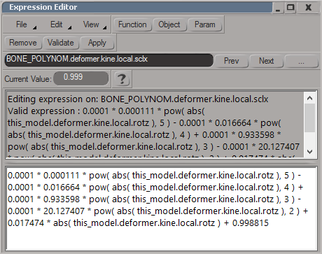
Rotation to scale correlation is very close to the original and when animated looks more or less clean (just a little bit wobbly, good enough for a demo):
Job done! Right?..
Nope.
So now we have a solution for deforming our mesh on one axis. For 2D animation you're set and can use this right away as well as move on and add dynamic behavior to the bone. But if you want to reproduce something like movement of a container along both X and Z (say, over the surface area of a table), you're in trouble. If you apply this function to both sclX and sclY and rotate the bone in both directions, you'll see this:
I know what you're thinking: "maybe this can be fixed if you rescale the bone again?"
Not quite. See, when you rotate the bone on, say, X axis, Z axis changes as well. And since scaling is calculated in local space... There is no way to correct the distortion on only one axis anymore and rotating the bone will just twist the mesh which we don't need.
To avoid this we could settle with only rotating the top deformer bone in one dimension and use the root bone to spin the whole mesh to orient our deformation according to the movement applied to the root bone...
Enough!
This is where I'll draw the line and will move on to another method. Don't get me wrong, it is possible to calculate the orientation vector from the movement of the root bone in global space and use this to orient the mesh. This would work for a "container" with liquid that is standing perfectly straight and translated around the scene along XZ-axis.
But then... Then you remember that the container can tilt. It can also be translated in a tilted position and even, God forbid, be lifted off the surface in a random orientation and transposed in all 3 dimensions which would also impose inertia upon the surface of our "liquid" mesh. Here's an example of how it should be able to behave being thrown around in the scene:
Also, keep in mind that the resulting polynomial coefficients (as well as those of my simple quadratic function) are only applicable for this specific mesh. You basically have to redo data analysis and approximation steps to ensure the mesh deforms without much noticeable abnormalities after each change to the diameter of the cylinder...
Oh, snap! The cylinder! What if the container was of a different shape? Now we really are in trouble. Rotating the mesh inside of an arbitrarily-shaped container is out...
ಠ_ಠ
Basically, there are lots of challenges to overcome, but whether you should take them on or not should always depend on the goal. In my case, I don't need to go and try to develop an all-encompassing bone-based dynamic sloshing liquid rig for a videogame (which would be an obvious use for such a bone-based rig). I need something less complicated that could work in my DCC to use for background secondary animation to add more production value to the final product in the form of a shot in an animated film. So let's just cut our losses and move along.
Blend shapes
Also known as Shape Keys or Moprh Targets, they are mostly used for facial rigging or for adding hand-sculpted details to the surface which would be difficult to achieve with skeletal animation alone.
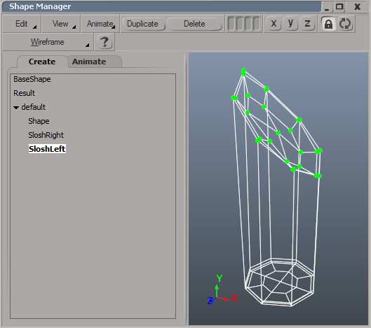
I wouldn't say I actually spent much time with this method since I quickly realized how complicated it might get. You would either need to have two morph targets for sloshing the "liquid" left and right and end up where we ended up in Skeletal animation. Otherwise you'd have to sculpt a large number of targets for various angles and interpolate between those.
Needless to say, that would be overly complicated as well as time-consuming, so let's finally settle with the final technique I could come up with.
Surface reprojection
What if you could actually shape the surface of the "liquid" mesh with another one, like a flat plane, "clamping it down" from above? Or rather, project some of the vertices of the "liquid" mesh onto another.
Enter the Shrink Wrap operator.
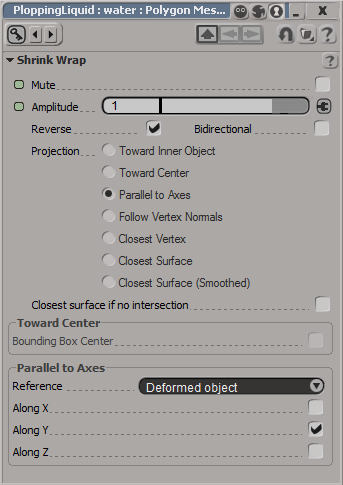
I'm sure you know what shrink wrapping means in CG. It's when one mesh gets literally "wrapped" around (or over, or under...) another one. Shrink wrapping has many applications: from placing decals on an uneven terrain to fitting clothes to a character.
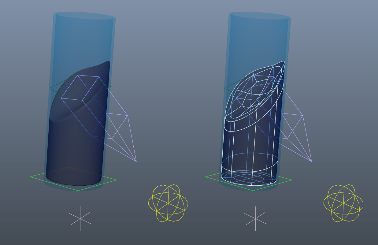
In our case we're interested in a particular mode called "Parallel to Axes". It casts a ray from each vertex of the mesh along selected axis and places those vertices on a surface of a mesh used as a "shaper". If there's no intersection of two meshes, vertex positions of the driven mesh are not affected.
A side note for Great Justice and to specifically avoid angry rants from Softimage ICE-only zealots: yes, one could achieve this with ICE by directly manipulating the points of the mesh through a custom network of ICE nodes. But I'm lazy and this deformer gets the job done, so I'll carry on.
Looks like this method could be the right one to get the job done! (spoiler alert: and it does, indeed).
Non-fluid "fluid" dynamics
Well now. We have chosen the technique to shape the surface of the "liquid" mesh. Armed with a basic mesh-shaping set-up we're finally ready to breath life into the rig and actually make he whole system dynamic.
Watching how liquid deforms in the real world, I broke the process into two steps:
- Make the surface shaper plane object wobble back and forth according to the movement of the container object.
- Add details to the ever-changing "liquid" mesh using per-point deformers.
Spring-driven surface dynamics
In the real world surface of any resting liquid in normal conditions is always horizontal. Then, when a container with liquid is translated in space, the surface of the medium rocks back and forth resembling spring-like motion ultimately coming to rest. Therefore, to emulate such behavior we could try constraining the shaper to a basic spring.
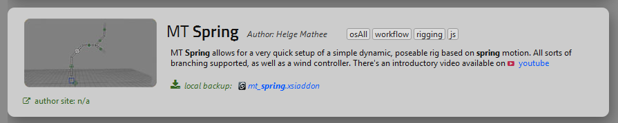
To avoid using XSI's "Tail" operator (which has... a number of issues), I looked around and stumbled upon MT Spring — a Scripted Operator-driven spring add-on developed by Helge Mathee.
Here's what I did:
- Created a "hanging" spring.
- Constrained the flat shaper object's orientation to that of a spring.
- Constrained the spring's parent position to the root_null parent of the shaper object placed directly in the center of the "fluid" mesh to allow it to only translate and not rotate together with the rig. This was to make sure the spring's resting state would always stay vertical and thus keep the surface of the "liquid" mesh horizontal in a tilted "container".
Here's what the rig looked like in motion:
Mt_Spring-based rig worked fine, but with a caveat: its decay rate was rather high. Even with decay set to zero, the spring would lose energy pretty quickly, making the "liquid" seem quite thick or viscous, sort of like hot chocolate or a smoothie. By tweaking the parameters and placing the "wind" control null further below the spring to force it to oscillate more, I was able to somewhat overcome this, but ultimately introduced jitter to the movement of the spring, since the increased effect of the "wind" null would decrease precision of the smaller movements of the spring and make it unstable under certain conditions.
I kept looking for an alternative spring solution.
I then tried the ICE strand dynamics framework (implemented in Softimage via ICE Verlet integration) to drive the simulation only to find out that it was not very "springy" (at least not on 23,976 to 30 fps timelines) and would lose energy even quicker.
So I finally decided to just bite the bullet and develop a math-driven spring-like logic in the form of a Softimage's Scripted Operator — a Python 2.7/Visual Basic/JavaScript-coded behavior script applied to an object in the scene.
An unforeseen discovery
While playing with the strand dynamics framework I found out that it supported mesh collisions which could be useful to drive dynamic bone chains as an option for secondary animation on background objects and characters: pieces of cloth in the wind, aprons, capes, ponytails, antennas, trees... Pretty cool!
But I digress. Back to rigging.
Spring-like follow scripted operator
The main property of any spring is, well... It's a spring. Therefore it has a resting position it's always trying to get back to, unless some forces prevent it from doing so. In this case the forces are gravity pulling the spring down and acceleration from the lateral movement of the spring base.
I need something like a pendulum to drive the shaper object, and make that pendulum react to the movement of the container in a decaying motion.
To avoid dealing with mass, angles, angular momentum and such I will do what I usually do whenever I can — I'll script the basic behavior and leave the boring math to the CPU. To do this, I will simply use two nulls: a Target null which will always rigidly follow the container and a Follow null which will accelerate in the direction of the Target null until it comes to rest.
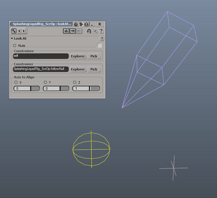
I will then use a "Look at" constraint on a Pendulum null which will always point to the Follow null.
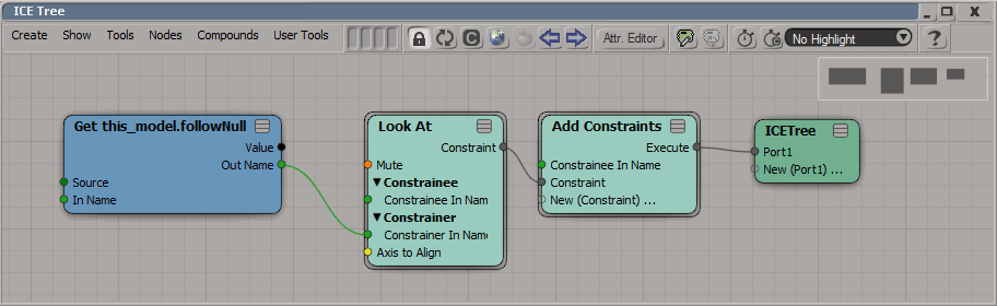
And voila! We have a functional pendulum! Now all we need to do is script the Follow null and constrain the shaper object's orientation to that of a Pendulum null.
After several hours of getting used to coding without any autocomplete (yeah, it's a bit bare bones, this Scripted Operator Editor) and recalling basic Linear Algebra I was able to script some dynamic behavior for my follow object. Since JavaScript doesn't have native support for vector math I simply used arrays to do the job:
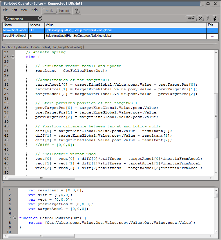
The "spring follow" logic exposes the most important configuration variables:
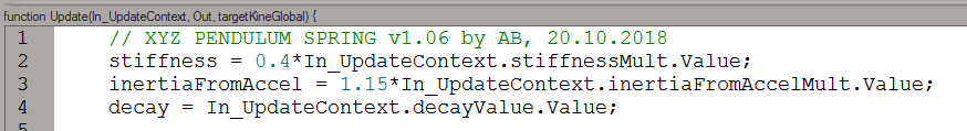
As you can see, due to the fact it's not using a closed-source physics core we finally have direct access to all variables used in the calculation and can modify those in some interesting artistic ways. For example, you can see that my inertiaFromAccel variable gets a 15% "boost" in a normal state and transfers more energy and momentum from the movement of the root object to the "liquid" shaper resulting in a less physically accurate, but a much more "dynamic" result. And, of course, I can now directly specify the decay value to make the liquid oscillate for as long as I need it to. This way I'm completely bypassing any energy loss which would happen If I were to use a real physics or a strand simulation engine.
Math rulez!
I can also customize how the system reacts to, say, acceleration of the target object so that additional acceleration would instead prevent the "pendulum" from keeping up with the container which would in turn make the "liquid" look thicker and more inertial as it "climbs" the container in the direction opposite to the acceleration.
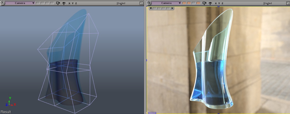
So without further ado, here's the result I was striving for all along trying to make the dynamics resemble that of a body of water (more or less):
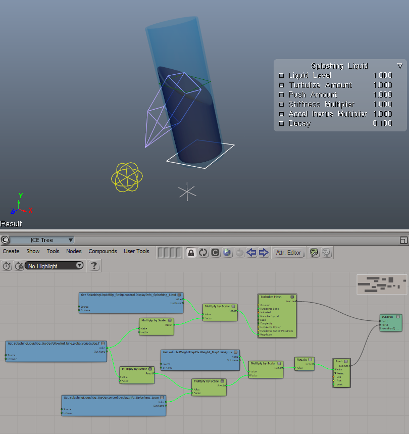
And here's what a completed rig looks like with all implicit control objects:
I used a similar approach when coding the character controller inertial movement for Run and Rock-it Kristie, except in Unity I utilized actual 3D vector-type objects from the scripting API in the form of a Vector3 struct which was quite a bit more convenient.
Oh, right... The SDK!
Uhm... This is embarrassing...
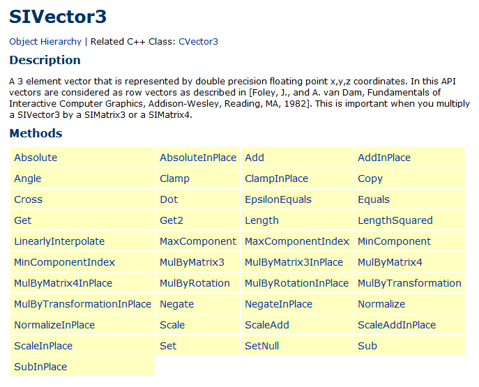
Being an amateur I didn't have much experience scripting in XSI as well as using Softimage's SDK reference guide. Therefore it was quite enlightening and entertaining to find out that Softimage actually did have an XSIMath object "that provided basic 3D mathematics functionality" with various utilities and methods like... The creation and manipulation of actual vector-type objects such as XSIMath.CreateVector3 which creates and returns an SIVector3 objects with a plethora of already available methods.
Oh well... At least I had some fun with my patented "head-on approach©" on the way as well as actually did manage to end up with a working solution. Win-win!
Seriously though, do study your SDK first before coding.
Note about Global and Local spaces
In case of dynamically driven rigs and other effects it's hard to overestimate the importance of doing calculations in Global space, rather than Local space of the object relative to its parent. It does add a bit of overhead to the calculations but makes it possible to use such rigs in any orientation and position in the scene whilst having them correctly react to the external forces.
Utilizing ICE for secondary deformations
Even though I ended up with a fully-functioning rig, something was missing... Looking at how water behaves in real life I immediately realized: the surface of the liquid deforms irregularly depending on whether it's closer to or further from the bounds of the container. Therefore I had to add some secondary deformation on top of my "liquid" mesh to try and emulate this.
To keep things simple, I split the deformation into two components:
- Denting or "dimpling" in the middle of the upper surface which happens when the body has angular rotational momentum causing redistribution of the liquid from the center of the spin towards the edges of the container.
- "Stretch"-like deformations at the edges due to the parts of the liquid surface that are the furthest from the center of the spin receiving the highest momentum.

To do this I will recycle and update the calculations done for the spring. Specifically, I need to know how much momentum the liquid receives at each given moment:

Diff is a variable used to store the position difference between target and follow nulls. I can use this to see how far the follow object is from the target and hence how much deformation should be applied to the deformers. Again, not physically accurate, but good enough to drive the deformations.
I will then use the new followAccel as a deformation strength multiplier for both effects:
- "Push" for denting in the middle.
- "Turbulize mesh" for uneven stretching of the vertices closer to the border.
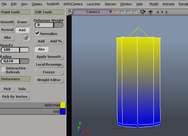
Now all I need to do is paint a couple of simple weightmaps:
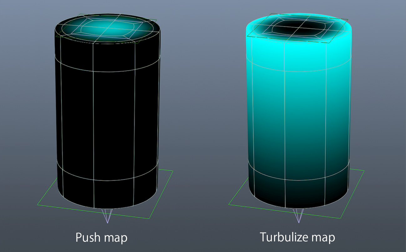
Note how Push will only affect the middle part of the surface and Turbulize — points which are closer the to the edges.
You can clearly see, how the distance between a Follow null (yellow) and a Target null (gray) affects the strength of the two deformations.
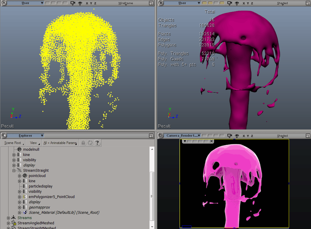
Now here's the original rig test scene, but with the added deformations:
Doesn't it look so much better with secondary deformations?
Just for my own reference, here's the set-up for a water-like behavior :
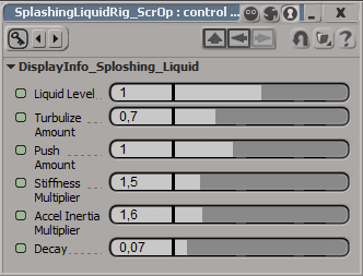
Liquid level control is also available:
The surface reprojection method can also be used with a mesh of a fairly arbitrary shape with both concave and convex curvature. Mesh topology should be appropriate for such deformations, especially if you're planning to subdivide it for a smoother result:
You could cheat even further and apply a deformer or a lattice on top of the rig (that is — after all of the dynamic deformers) to sculpt it into whatever shape you need or even create different blend shapes to easily switch between different looks for the rig!
This also shows how powerful and versatile XSI Softimage is (was?.. Uhm, no. It's still does the job for me). I was able to try out all of these techniques in XSI without any issues and in the end its powerful tools allowed me to finally produce this rig. If there's something you can imagine, you can probably recreate it in XSI. If you can get a copy, that is.
But wait, there's more!

In my next post in the series I will attempt to go even further and produce a final production-ready asset for the film in the form of a strawberry milkshake with foam and some cool additional effects!
Stay tuned!